Capstone Project, Robot Manipulation
The purpose of this final project, is to perform a pick-and-place operation of a 5x5 cm cube, with the youBot mobile manipulator (a mobile base with four mecanum wheels and a 5R robot arm).


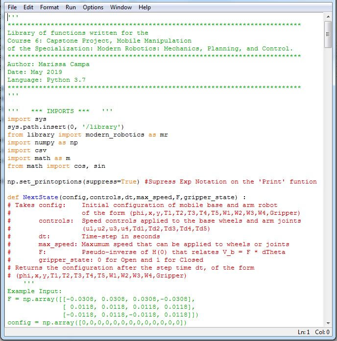
Here I developed a program that integrates the concepts I learned throughout the courses, such as direct and inverse kinematics of mobile robots and robot arms, including exponential coordinates and homogeneous transformation matrix, as well as trajectory generation of a reference position, feedback and feedforward control and odometry for position estimation.
The program takes as input the initial and goal configurations of the cube, the reference initial configuration of the youBot, the actual initial configuration of the youBot (different from the first reference), and the gains of the feedback controller.
First, it creates the reference trajectory for the end-effector (gripper), divided in 8 segments:
-
Move to gripper from its initial configuration to a "standoff" configuration above the cube.
-
Move the gripper to the grasp position.
-
Close the gripper.
-
Move the gripper to the "standoff" configuration.
-
Move the gripper to a "standoff" configuration above the goal configuration of the cube.
-
Move the gripper to the goal configuration of the cube.
-
Open the gripper
-
Move the gripper back to the "standoff" configuration.
Each configuration in the reference trajectory is an homogeneous transformation matrix, from the origin frame {s} to the end-effector frame {e}, of the form:
T_se = [ r11, r12, r13, px ]
[ r21, r22, r23, py ]
[ r31, r32, r33, pz ]
[ 0, 0, 0, 1 ]
Expressed in an array of the form:
[r11, r12, r13, r21, r22, r23, r31, r32, r33, px, py, pz ]


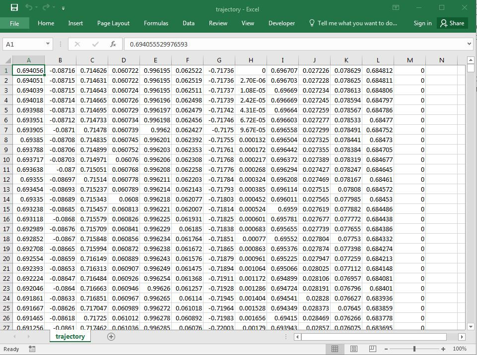
Then, it enters a loop with a feedback plus feedforward controller that takes with each step, it calculates the control speed commands that would take the robot from the actual to the reference configuration. A controls array has the form: [u1,u2,u3,u4,dT1,dT2,dT3,dT4], where u1 to u4 are the mobile wheel speeds, and dT1 to dT5 are the arm joint speeds.
In the second section of the loop, with the speed commands, it performs Odometry, that calculates the next configuration of the robot, at the next timestep of 0.01s, using direct kinematics.
Each configuration of the robot is an array of the following form:
[phi, x, y, T1, T2, T3, T4, T5, W1, W2, W3, W4, Gripper ]
Where:
{phi, x, y} are the coordinates of the mobile base in the world frame.
{T1, T2, T3, T4, T5} are the joint angles of the robot arm.
{W1, W2, W3, W4} are the mobile base wheel angles.
{Gripper} is the end-effector (gripper) state, 1 for close, 0 for open.
The following arm joint limits were used:
lower_limits = (-2.5, -1.17, -1.2, -1.1, -2.8)
upper_limits = ( 2.1, 0.2, 0.25, 0.1, 2.8)
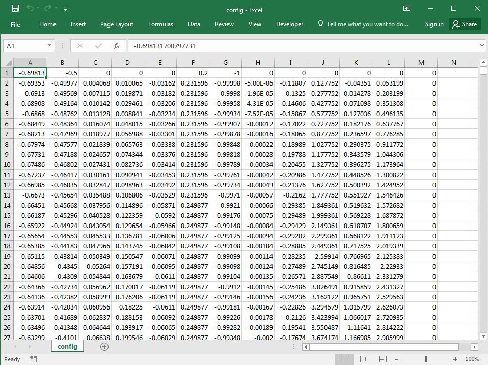
Finally, it saves a .csv file with all the calculated robot configurations caused by the feedback control speed commands, as it navigated through the reference trajectory. This file is then used by the software V-REP to simulation the robot motion.


======== BEST RESULT ========
A 'Feedforward plus P' controller was used with a proportional gain 2.8. Maximum speed for wheels and joints: 15 rad/sec
First reference trajectory with configuration
chasis(x:-0.3, y:0, phi:-10) joints(0,0,0.2,-1,0)
Robot offset from first reference trajectory
chasis(x:-0.2, y:0, phi:-30) joints(0,0,0,0,0)
Best Result


============== NEW TASK =================
A 'Feedforward plus P' controller was used with a proportional gain 3.1. Maximum speed for wheels and joints: 15 rad/sec
First reference trajectory with configuration
chasis(x:-0.3, y:0.05, phi: 5 (degrees) ) joints(0,0,0.2,-1,0)
Robot offset from first reference trajectory
chasis(x:-0.2, y:0, phi: 30 (degrees) ) joints(0,0,0,0,0)
Cube initial configuration x: 0.7, y: -1.2, phi: -45(deg),-0.78(rad))
Cube goal configuration x: 1.2, y: 0.2, phi: 10(deg),0.17(rad))
New Task
Challenges...
One of the challenges for me was implementing joint angle limits to the control loop. It had a comparator, so that if a joint was to be beyond the limits, it would zero-out the corresponding column in the Jacobian matrix, and then calculate again the necessary twist with the remaining columns, but sometimes when calculating again, the pseudo-inverse function calculated a speed opposite to the previous one, causing a few "spikes" in the movement. It smooth out by finding the correct combination of joint angle limits. Also finding the correct feedback gains for the best result.
I used Python 3.7 to develop this program, with the libraries numpy and csv. I also used the library 'modern_robotics' provided in the Modern Robotics wiki website.
http://hades.mech.northwestern.edu/index.php/Modern_Robotics
For the simulations, I used the software V-REP EDU PRO software.


I followed the assignments in the Course 6: Capstone Project, Robot Manipulation, which is part of the online specialization Modern Robotics: Mechanics, Planing and Control, offered by Nortwestern University and Coursera.