Speed and point-to-point control for trajectory tracking of a Skid-Steered Mobile Robot
(Master thesis)
My master thesis consisted in the design and implementation of an autonomous navigation method, based on speed and Point-to-Point control to achieve trajectory tracking of a skid-steered mobile robot.

This project is divided in four sub-systems:
-
Trajectory Tracking System
-
Point-to-Point Control System
-
Speed Control System
-
Pose Estimation System

A skid-steered mobile robot (SSMR) is a differential drive type of robot, where the movement of the robot is caused by the speed difference between the left and right sides.
Here is a video of the experiments I conducted with a skid-steered mobile robot. In the first two clips, the robot is given a single reference point in the X-Y plane, and the robot performs pose control using pose estimation to determine the error of the actual pose of the robot and the reference point, and then calculate the necessary speed commands. Finally the speed control system utilizes encoder information as feedback to the R-S-T speed controllers. In the last clip the robot is given a reference trajectory to follow.
Note: A trajectory tracking system (computer vision) was used to monitor the performance of the algorithms developed for this thesis. Special thanks to the developer of that system, Dr. Manlio Barajas.
Autonomous Navigation: System Architecture
Autonomous navigation is an active research area that involves many different techniques and disciplines. Depending on the application, we can have a high level planning system that oversees the required tasks and how to accomplish it. For example, if a robot needs to go from one room to another, or from one building to another.
There is also a low level planning and control that determines the exact commands that will drive the robot through the required trajectory. For example, once we know the reference points, it will send speed commands according to the actual pose of the robot.
Here is an overview of the system architecture that shows one method for achieving autonomous navigation. The subsystems I focused on for this project were: trajectory tracking, point-to-point, speed control and pose estimation.

Here is an brief explanation of the inputs and outputs of each of the four sub-systems.
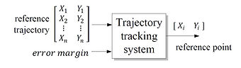
The Trajectory Tracking system receives a set of reference points (Xr , Yr) for the robot to follow. It uses the position of the robot and determines which point will be followed.

The Speed Control System takes the desired left and right speeds and levels the robot wheel speeds using the digitally desiged R-S-T controller.

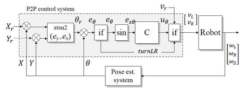
The Point-to-Point system is designed to reach a reference point in X-Y. Pose estimation is used as input, and converts the position error to left and right reference linear speeds.
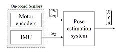
The pose estimation receives information from on-board sensors like encoders and an IMU gyro, and it estimates the position of the robot.
Kinematic Model for Pose Estimation
The Pose Estimation system, also known as odometry, uses the kinematic model of the skid-steered mobile robot. It converts the motors angular speeds (from encoders) and gyroscope values from the IMU (Inertial Measurement System) sensor, to global coordinate linear and angular speeds. Then, it uses discrete integration to calculate the step displacements in meters that accumulate over time.


Point-to-Point Control with PID
The point-to-point system controls the direction to the robot, sending speed commands to reduce the error from the current robot pose and the reference point. It uses a PID control loop that takes as input the orientation error and determines the linear left and right velocities to send to the speed control system.

Dynamic Model for Speed Control
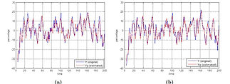
A dynamic model of the robot was obtained through an approximation to a discrete transfer function. The values are obtained using the least squares method, using values from a RBS (Random Binary Sequence) test, where pseudo-random open-loop speed commands obtain an array of input-output responses.


The R-S-T controller is composed of various digital discrete filters that process different signals from the system. The filter S processes the control signal, the filter R processes the value of the plant and the filter T processes the reference signal. Each side of the robot have a speed controller implemented.


Software Implementation
The software platform used to implement the developed control algorithms is ROS (Robot Operating System), a very powerful robotic tool which is an open source that allows executables to be individually designed and coupled at runtime. The main programming language is C++.
-
The User Interface node (HMI) is subscribed to all the other nodes, and the relevant information is displayed.
-
The Trajectory Tracking node receives the desired trajectory from the HMI, and the pose of the robot from the Pose Estimation node and it publishes the current reference point.
-
The Point-to-Point node is subscribed to the reference point and to the pose of the robot, it publishes the reference speeds.
-
The Speed Control node is subscribed to the reference speeds, and it publishes speed commands in (0-100%).
-
The Pose Estimation node is subscribed to the sensor information and publishes the pose of the robot.
-
The Jaguar-4x4 node establishes the wireless communication from the computer to the robot, it is subscribed to the speed commands (0-100%) and it publishes the sensor information.

The User Interface was developed using Qt-Creator, and it interacts with the rest of the nodes in ROS. The main window can be used to load the desired trajectory from a file in the computer, and it displays information from the on-board sensors, as well as the estimated pose of the robot, information from the point-to-point system and speed control.


Experiments and Results
The figure in the left shows the R-S-T speed controller for the left and right sides. The controller was designed as a second order model, with a time rise t r = 2 sec and an overshoot of %Mp = 0.01 % . The figure in the right, shows the trajectory tracking error in X and Y axis and the Euclidean distance ρ. In the ρ plot, the distance reduces as the reference point is being approached, when is less than 0.5 m, then ρ increases when the next reference point is set.


Here is a composition figure that shows the skid-steered mobile robot in the trajectory tracking experiment. The robot was assigned a reference trajectory through the user interface with three reference points. The figure shows the successful arrival of the robot to each of the reference points.

Final thoughts...
This project was an amazing learning process for me, and a very interesting challenge. It allowed me to apply concepts like kinematics, dynamic process identification, control algorithms and software development to a real-world robotic platform. What I liked more about this project was translating control algorithms to programming language and conducting experiments. The most challenging part for me was the implementation of all the different systems with ROS nodes and the interaction of the messages with subscribers and publishers.
Acknowledgments
Thanks to my advisor, Dr. José Luis Gordillo for sharing his knowledge and for guiding me throughout my masters. Thanks to the members of my thesis committee, Dr. Rogelio Soto and Dr. Ernesto Rodrı́guez, for your advice and constructive observations, it surely has helped me expand my knowledge and objectives. A kind acknowledgement to Dr. Manlio Barajas for sharing his vision tracking system. I’m very grateful I was presented with the opportunity to work with this very competitive team that the eRobots research group is.
I would like to thank the Tecnologico de Monterrey and the Consejo Nacional de Ciencia y Tecnologı́a CONACYT for the scholarship support and the amazing graduate experience.
The Jaguar 4x4 Skid-Steered Robot is sold by the company Dr. Robot.

Project developed with ROS (Robot Operating System) and C++ language.

